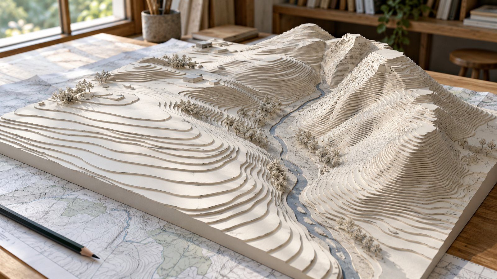
Topographic maps appear throughout Programming & Analysis (PA) and Project Planning & Design (PPD). A question might ask where water will collect, which part of a site is flattest, where a building or parking lot should go, or how much a path rises. Almost all of them depend on reading the contours correctly — and a handful of rules does most of the work.
Rule 1: each line joins points of equal elevation
A contour line connects every point on the ground at one elevation. Walk along a contour and you never go up or down. Two consequences follow:
- Contour lines never cross (one point can’t have two elevations) and never split.
- Water flows perpendicular to the contours, from higher lines toward lower ones — it never flows along a contour, because along a contour there is no slope.
Each map has a contour interval, the elevation difference between neighboring lines — for example, 1 ft, 2 ft or 5 ft. Labels on some lines (often every fifth, drawn heavier) tell you which direction is up.
Rule 2: spacing tells you the slope
The closer the contours, the steeper the ground. To put a number on it:
slope = vertical rise ÷ horizontal distance
With a 2 ft contour interval:
- lines 40 ft apart → 2 ÷ 40 = 5%
- lines 20 ft apart → 2 ÷ 20 = 10%
- lines 10 ft apart → 2 ÷ 10 = 20%
Evenly spaced lines mean a uniform slope. Lines that are close together at the top of a hill and spread out toward the bottom describe a concave slope; the reverse describes a convex one.
Rule 3: the V-rule — valleys and ridges
Where contours cross a stream, swale or valley, they bend into a V that points uphill, toward higher elevation. Where they cross a ridge or spur, the V points downhill.
The easiest way to remember it: water carves the ground, so contours bend back upstream to find the same elevation on both sides of the valley.
Putting it together: a site question
Suppose a site slopes down from north to south, with contours at a 2 ft interval. Halfway across, the lines form Vs pointing north. Here’s how to read it:
- Find "up." The labels increase toward the north, so north is uphill.
- Find the drainage. The Vs point north — uphill — so they mark a valley. Surface water from both sides will gather there and run south.
- Find the buildable ground. Away from the valley, where the contours are widely spaced, the ground is flattest — the natural place for a building pad or parking.
- Check the consequences. Placing a building across the valley would block natural drainage; you would need to redirect water around or under it.
Contours in grading plans
On grading plans, existing contours are usually drawn dashed and proposed contours solid. Where a proposed line departs from the existing one, the ground is being changed: a proposed contour moved downhill from its existing position means fill has been added there; moved uphill means cut.
Grading questions often ask you to keep water moving away from a building. The test is simple: right next to the building, the proposed contours should show ground falling away from the walls, not toward them.
Practice routine
- Take any site plan and mark north/uphill first, every time.
- Draw arrows perpendicular to the contours to show where water goes.
- Calculate the slope at two or three points using the interval and the scale.
- Circle the valleys and ridges using the V-rule, then check them against the labels.
The PA exam guide and the PPD exam guide show where site analysis fits within each division.