A beam can satisfy a strength check and still move too much for its finishes or use. Learn to identify the governing problem, calculate a given span-based limit, and compare deeper framing with added supports at ARE concept and basic-application level.
A reading-room floor may carry its required load yet move enough to damage a sensitive finish. Calling it "strong enough" does not resolve that serviceability problem. American Wood Council joist tables check stiffness and bending strength separately.[4]
This lesson applies to structural-system selection and coordination in PPD and component sizing and detailing in PDD. Those connections follow NCARB’s current ARE 5.0 Guidelines, effective October 1, 2026; they are a study application, not a claim that a particular question will appear.[1] [2] The practice questions are original KPath scenarios, not actual ARE questions.
A floor passes strength, but the ceiling may crack
Watch the member bend
Illustrative bending is exaggerated. No displacement, capacity, or engineering result is calculated.

Original member: movement grows as the illustrative load is applied.
End positions are held at the supports. The curve illustrates flexure only; it does not verify strength or vibration performance.
Understand the mechanism
Flexural deformation depends on the material’s modulus of elasticity, the section’s geometry, load, span, and support conditions. AWC’s 2024 Span Tables, Appendix A, presents these variables together for a simply supported beam under uniform load.[3] Here, use that relationship qualitatively; no full beam-equation calculation is needed.
Greater section depth can improve flexural stiffness, but it also occupies ceiling space. The architectural decision includes clear height, duct routing, connection space, and overall floor-to-floor height. A different section is a proposal to check, not an automatic solution.
Change one condition: If the ceiling height is fixed and deeper framing will not fit, B is no longer an uncomplicated choice. Explore a different section or structural arrangement with the engineer. If a central support is allowed, the answer may shift toward a shorter-span layout.
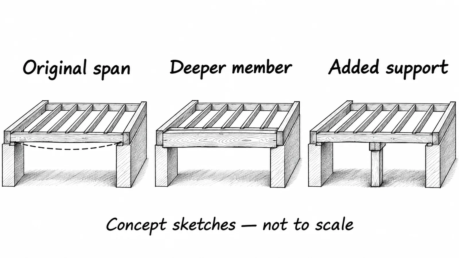
Compare depth and support
Illustrative bending is exaggerated. No displacement, capacity, or engineering result is calculated.

Original member: movement grows as the illustrative load is applied.
For the support option, two simple spans are drawn to show the concept. A column beneath a real continuous girder changes its behavior and must connect to a valid support below. The visual differences are qualitative, not comparative calculated deflections.
Strength and stiffness: read the clue, then choose the check
| Question | Strength | Stiffness / serviceability |
|---|---|---|
| Main concern | Resistance to required forces and failure modes | Movement under the specified loading |
| Typical clue | Capacity is inadequate | Predicted deflection exceeds the stated limit |
| Useful evidence | Member resistance and demand | Predicted movement, span, limit, load case |
| Important boundary | Passing does not prove acceptable movement | Passing does not prove adequate strength |
AWC’s span-calculator documentation also distinguishes bending, deflection, shear, and bearing inputs.[5] Do not reduce an entire framing design to one successful check.
For drawing questions, start at the supports. Identify the member being evaluated, follow its load path, and locate any change in support. A column below a girder can change that girder’s behavior without changing the length of every secondary member above it.
What does L/360 mean?
In a span-based criterion, divide the defined span by the stated denominator to obtain a displacement limit. Use consistent units and the criterion’s definition of span. AWC’s floor-joist tables provide an example of an L/360-based check; that is not permission to apply L/360 to every structural member or finish.[4]
Original teaching assumptions: a simply supported member spans 18 ft; the question specifies an L/360 live-load deflection limit; predicted live-load deflection is 0.55 in. Strength and all other checks are outside this example.
216 in ÷ 360 = 0.60 in
18 ft × 12 = 216 in. Predicted 0.55 in ≤ allowed 0.60 in: passes this deflection check.
Now keep the same member and predicted movement, but assume the project specifies L/480 for the same loading:
216 in ÷ 480 = 0.45 in
Predicted 0.55 in > allowed 0.45 in: fails the stricter check.
The larger denominator permits less movement. The beam did not become weaker when the criterion changed; the acceptable displacement became smaller. The L/480 criterion here is a stated project assumption, not a universal finish requirement.
Change one condition: With a given L/240 limit, that same 15 ft span allows 0.75 in. Compare predicted and allowed displacement only when both refer to the same load case and span definition.
A new support helps only if it fits the load path
Change one condition: If the proposed column lands above an unsupported area on the level below, the solution needs further structural coordination. A mark on one floor plan is not a complete load path.
A short review method for ARE questions
The KPath Four-Clue Check is an editorial study method: member → loading → limit → constraint. Identify the member and supports, match the loading to the reported displacement, read the actual acceptance criterion, then test the proposed fix against the room and systems.
- Do not compare live-load movement with a limit for a different load combination.
- Do not assume a stronger material designation guarantees the stiffness improvement needed.
- Do not treat visible cracking alone as proof of one particular structural cause.
- Do not treat a static deflection pass as a complete vibration assessment.
For cantilevers, continuous members, long-term behavior, and sensitive finishes, read the specific definition, assumptions, and applicable provisions. This lesson’s numerical examples are limited to the stated simple-span checks.
Quick questions
Does L/480 permit more movement than L/360?
No. For the same span, dividing by 480 gives the smaller allowable displacement.
Should I always choose a deeper beam?
No. It is one candidate. Available depth, load path, headroom, cost, and coordination may favor another approach.
Does passing deflection mean the structure is fully checked?
No. This is one serviceability check. Strength, other failure modes, and other project requirements remain relevant.
Continue with how PPD system choices develop into PDD details, or use the free ARE Knowledge Check. A short check is practice, not a prediction of exam readiness.
Continue in the KPath course
Continue with the related KPath lessons.
Understand what controls beam deflectionSHR.D3.DEF.001 Reduce deflection with the most effective design moveSHR.D3.DEF.002 Know why deflection limits existSHR.D3.DEF.003 Differential movement, deflection, and serviceabilitySHR.D3.MOVE.002Lessons open in your KPath account — sign in or create a free account to continue.
Sources and further reading
The scenarios and animated labs are original KPath teaching material, not actual ARE questions or engineering guidance.
- NCARB ARE 5.0 Guidelines, effective October 1, 2026. PPD 3.2 and PDD 1.3.
- NCARB: Project Development & Documentation scope.
- American Wood Council: 2024 Span Tables for Joists and Rafters. Appendix A.
- AWC: How are the floor joist span tables calculated and used? (2021).
- AWC: Span calculator help. Note its stated 2012 NDS basis.